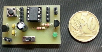
CW beacon with custom text using Atmel ATTINY85 MPU. The design includes the ability to change the message and speed
This little beacon measures 27X40mm, draws a measly 3.6mA in standby and less than
15mA key down and is powered by a 9-
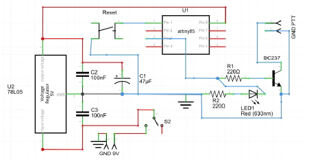
The schematic below shows how simple it is using minimal components to create a beacon for your radio station or for a Fox transmitter.
Components
The components list is short and sweet, 2 X 220R resistors (current limiting), 1 X 3mm LED, 1 X BC237 transistor, 1 X 78L05 voltage regulator, 2 X 100nF ceramic capacitors, 1 X47uF capacitor, 1 X reset push button switch, 1 X on / off toggle switch, 1 X 8 pin IC holder, 1 X Attiny85 and a PCB. You can build this on a small piece of vero board if you like. The PCB and source code will be listed at the end of the article for download from the website.
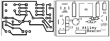
Construction
Construction is straight forward, starting with the smaller components; solder these in place making sure that there are no shorts between tracks. Next, add the larger components leaving the Attiny chip for last. Once completed, check again to make sure that there are no shorts between tracks and that electrolytic capacitors and transistors are fitted with the correct polarity.
Programming the Attiny85
To program the Attiny with your message, fit the Attiny to the programming interface in my projects page, or if you choose, use an AVR programming device such as the USBASP programmer. Open the Arduino IDE, select file, examples, ArduinoISP. Select tools, board and select Arduino Uno. Upload the ISP. Your Uno is now ready to program the Attiny chip. Place the programming interface on top of the Arduino making sure that the pins are matching in the headers. Open the KMDAttiny85CWBeacon.ino file (downloadable from the website). Select board, Attiny85 (internal 1MHz clock). Edit the beacon message where I have prompted for message and delay. Upload to the Attiny, Ignore any error messages, as this seems to be a versioning compatibility issue, the program does successfully load. You are now complete, remove the Attiny from the programming interface and insert it into the beacon board. Apply power to the board and in the preset delay time the LED should start flashing your message. Connecting this to your radio using the correct cables I leave up to you.
Please send me pictures of your beacon so I can show them in future articles, mails can be sent to projects@zs6kmd.za.net – PCBoards and kits will be made available through the website for those interested in building this project.
Source Files
ZS6KMDAttiny85CWBeacon – http://www.zs6kmd.za.net/ZS6KMDAttiny85CWBeacon.txt (right click and save as)
PCB Files – http://www.zs6kmd.za.net/ZS6KMDAttiny85CWBeacon.rar
73
ATTINY85 CW Beacon