KMDuino Bootloader - Home design Arduino UNO R3 Bootloader Shield for use with KMDuino
MKII
Right so now we all have an Arduino that we can play with, some may have a true blue one; others may have built my KMDuino. Our next step is to start building something useable. A handy little shield (working modules that fit on top or stack are called shields) to have in your goody box is a Bootloader. If you purchase blank Atmega 328P chips and want to load them, this will make it a piece of cake.
The PCB design is done in such a way as to utilise the existing pins on the KMDuino and these will just plug in on the bottom of the board in matching female header strips.
The circuit below is simple to follow and is used extensively as an ISP or In Circuit Programmer.
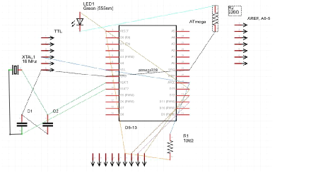
How it works is that we are using the ISP pins on the KMDuino to send and receive the data between the two devices. Now in the process of making the board as small as possible I never added an ISP socket, hence the idea of building a shield that takes care of everything.
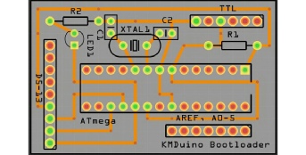
We will pick up the power to the Bootloader Shield from the TTL pins 4 and 6, The MOSI, MISO and SCK pins are pin 17, 18 and 19 respectively on the blank Atmega 328 and are connected to D11, 12 and 13 on the KMDuino. Reset is connected to D10 with a 10K ohm resistor from +5V. Because we want to program the device using its own clock source, we have added a 16mHz Xtal and two 22pF capacitors. Lastly we have added an LED and pull up resistor to display the read/write function (it will flash during the upload process).
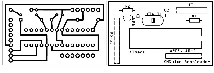
The board that I have designed is a little smaller than the KMDuino as we do not need the 5V regulator, the reset switch and the associated components. Once again, if you would like to make your own boards, the files are available on my website and are listed at the end of the project.
Components:
1 X 28 pin IC socket, 1 X 16Mhz Xtal, 2 X 22pF ceramic capacitors, 1 X 220 Ohm resistor, 1 X 10K ohm resistor, 1 X green 3.2mm LED, some female headers and the PCB.
Construction:
Construction is started by inserting the two capacitors and the 16mHz crystal, solder these in place and trim the leads short. Next we insert the LED and take note of the orientation, add the 220 ohm resistor and the 10K ohm resistor. Insert the IC socket and tack two opposite pins to hold it tightly in place while you solder the remaining pins.
A small modification to the TTL pins on the Bootloader is required, once plugged in to the KMDuino we will not be able to program the new device unless we extend the pins through both sides of the board. It is simple to add a strip of male header pins on top once the female headers are soldered below. Finally you can add the remaining female headers at the bottom of the board. These are made up of one section of 6 holes, one section of 9 holes and one section of 7 holes.
At this stage, check your soldering to ensure that there are no solder bridges or bad joints. Once you are sure then your board is complete and ready for use.
To use the board, just insert it on top of the KMDuino, insert the blank Atemega chip, connect to your computer through the TTL socket as normal (remember we added TTL pins on top of the Boot Loader which feed through to the TTL below). Open the Arduino software, select tools > board menu for the board you want to burn the boot loader for (we will use Arduino UNO) and then select Burn Bootloader > Arduino as an ISP.
Congratulations, you have successfully created your own Bootloader Shield and programmed a blank Atmega 328 chip with the bootloader.
PCB Files: http://www.zs6kmd.za.net/bootloader.rar
Happy Building
The KMDuino MKII is available as a kit with all components and PCB from my product page.
Happy building
73